 EMBEDDED SYSTEMS · TEAM PROJECT
Vandalism Resistant Speed Enforcement
Doppler radar, deterministic scheduling, custom signal conditioning, and stereo computer vision.
View case studySelected work in mechatronics, embedded control, robotics, instrumentation, manufacturing, and system testing.
Peter Marchut · Ontario Tech University · B.Eng. (Hons.), Mechatronics · April 2026Three multidisciplinary systems, documented from requirements and architecture through testing and iteration.
EMBEDDED SYSTEMS · TEAM PROJECTDoppler radar, deterministic scheduling, custom signal conditioning, and stereo computer vision.
View case study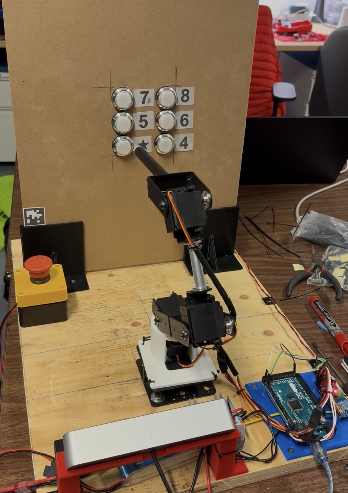 CAPSTONE · THIRD PLACE
A user-centred, wheelchair-mounted manipulator for restoring independence in everyday tasks.
View case study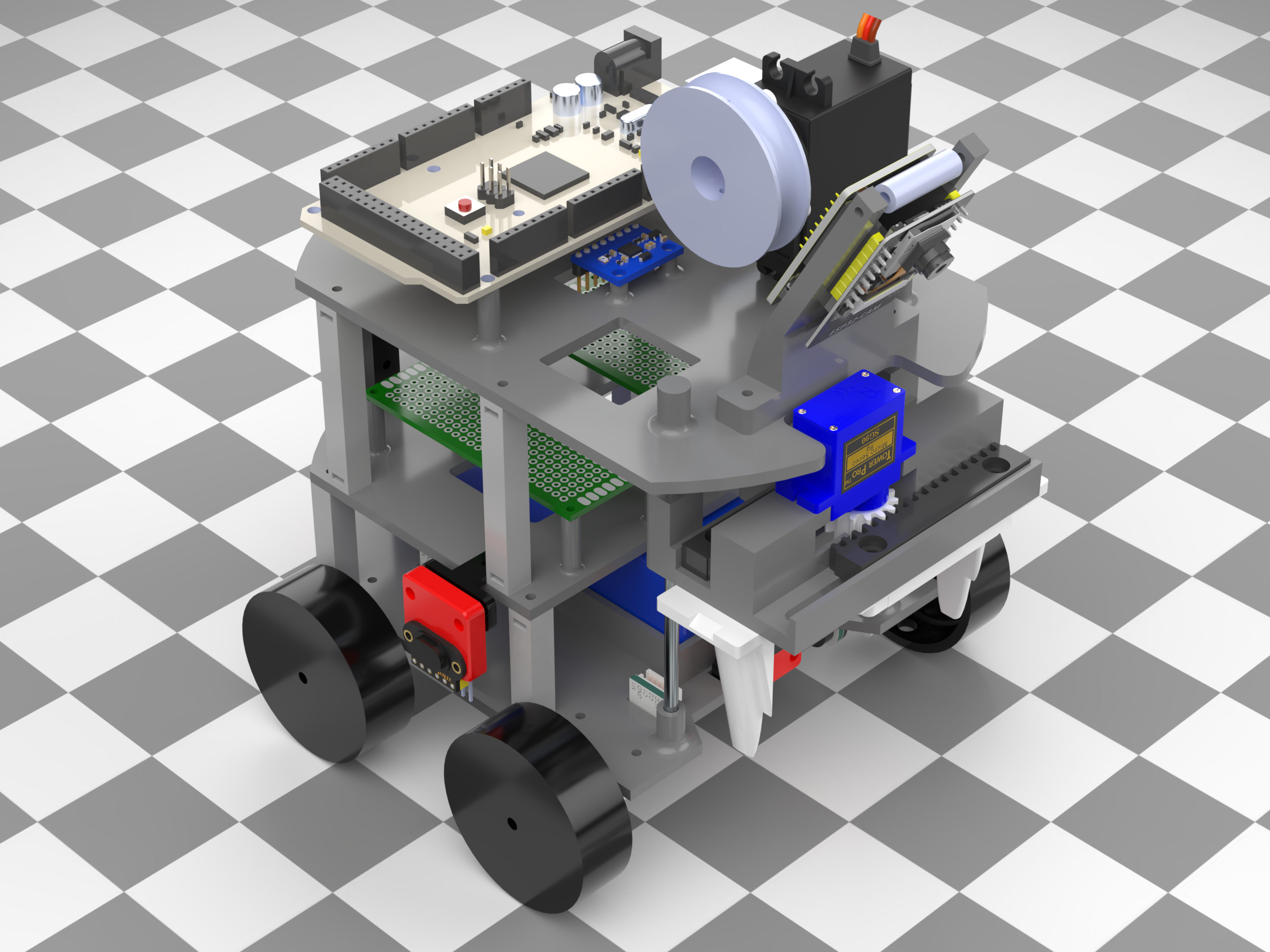 MECHATRONICS · THREE PHASES
One platform evolved through mobility, manipulation, sensing, and autonomy challenges.
View case study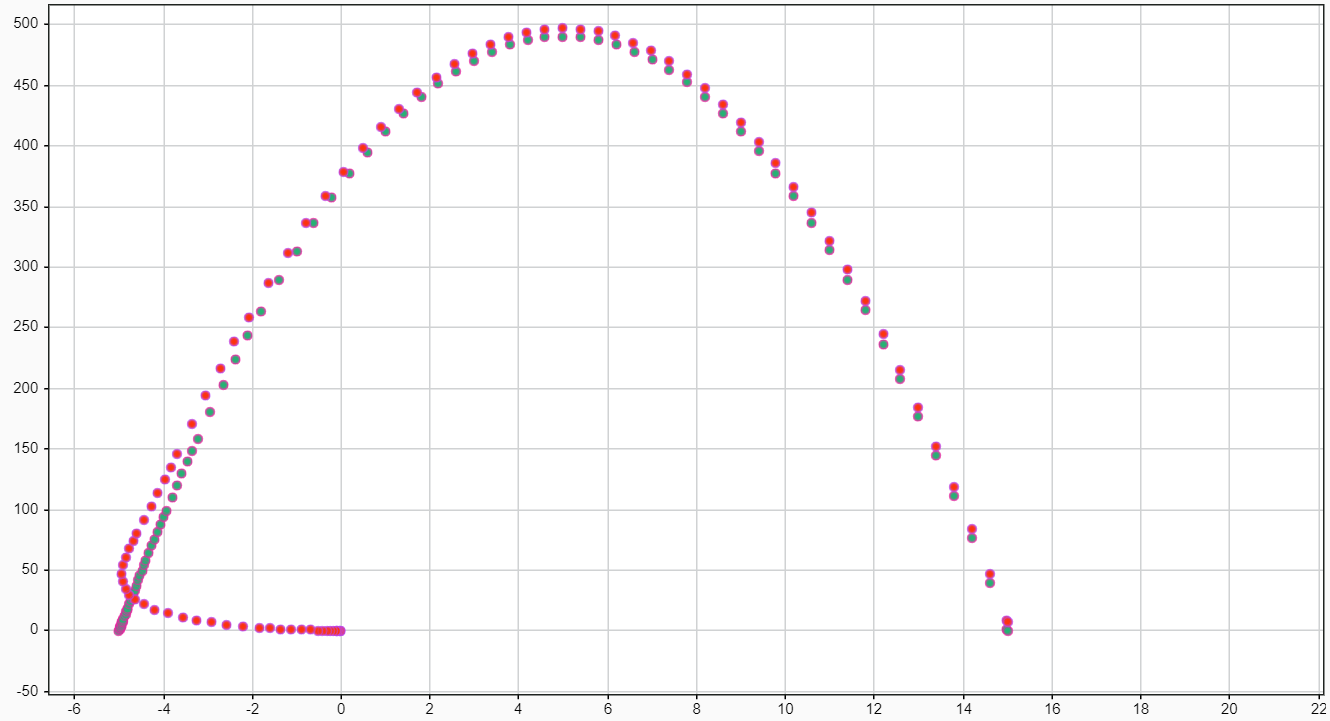 SYSTEM MODELING · TEAM PROJECT
Power electronics, actuator selection, and PID control integrated in a two-axis simulation model.
View case studyA compact, elevated speed-enforcement prototype combining Doppler radar, deterministic control, adaptive illumination, and stereo computer vision.
Conventional roadside speed cameras are vulnerable to vandalism. The team’s design goal was to reduce system size and weight enough for installation on existing elevated infrastructure—without sacrificing capture timing, night operation, or multi-target identification.
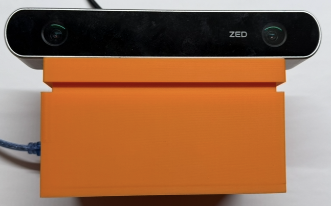
An HB100 Doppler sensor measures approach speed while an Arduino Mega 2560 executes the real-time control schedule. A ZED 2 stereo camera and computer-vision pipeline track multiple objects, estimate depth-based velocity, and match the correct target to the radar measurement.
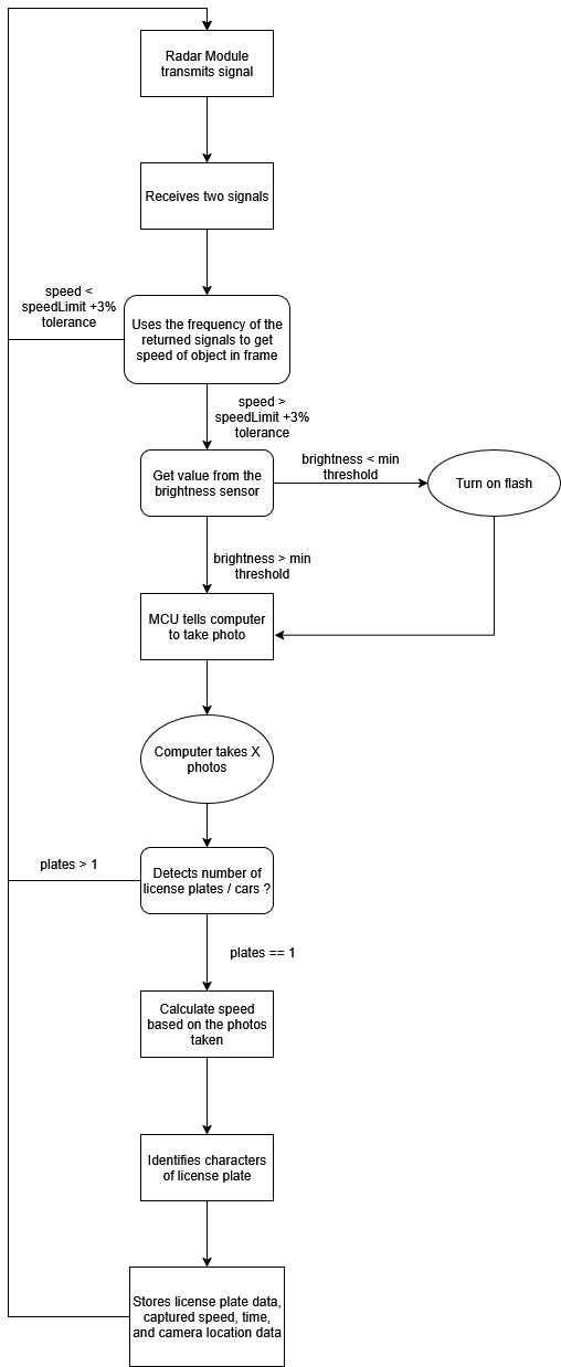
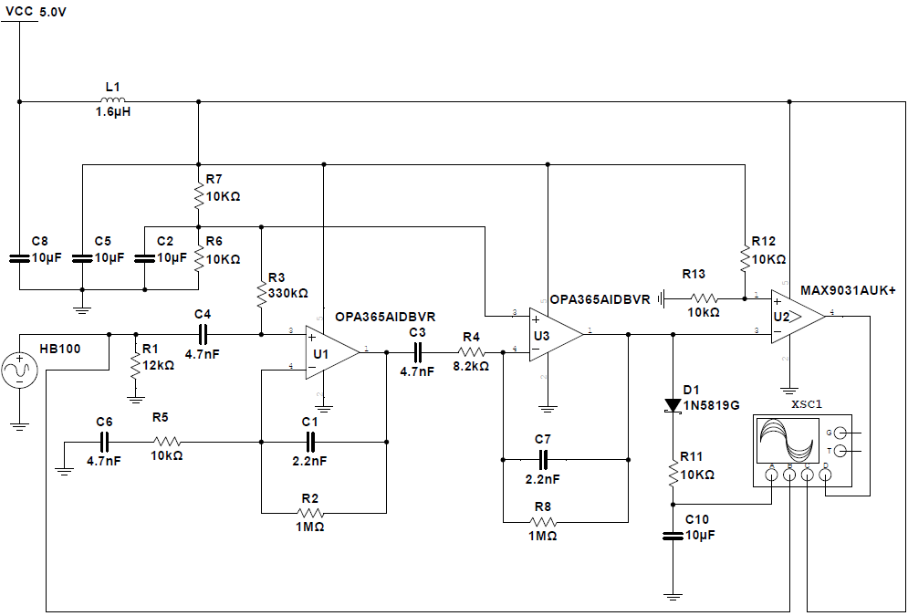
The raw HB100 output was too small for direct microcontroller input. A custom two-stage active band-pass filter amplified frequencies from 152 Hz to 4.34 kHz, rejected noise, and used an analog comparator to produce a 0–5 V square wave.
After Multisim validation, the team assembled the custom PCB by hand and confirmed reliable frequency counting and speed measurement.
The report distinguishes the 50.3 ms radar sampling interval from shorter calculation and output operations. A 250 ms frame-based schedule kept sensing and control predictable while image processing ran on a separate subsystem.
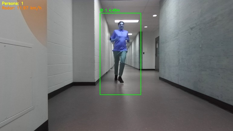
Logic-analyser and real-world tests verified the timing model. The prototype reacted to ambient-light changes in under 31.5 μs, sampled radar speed in 50.3 ms, and consistently measured moving-object speed within 2 m/s.
Arduino Mega 2560 · HB100 Doppler radar · ZED 2 · OpenCV · Multisim · custom PCB design · C/C++ · Python
A personalized robotic system designed with a client to restore independence across everyday tasks—beginning with reliably operating elevator buttons.
The project began with a client living with cerebral palsy and limited upper-limb mobility. Interviews, a modified Barthel Index survey, and occupational-therapy feedback identified the tasks with the greatest impact: leaving home independently, operating lights and elevator buttons, and using access fobs—all through a control method requiring minimal physical and cognitive effort.
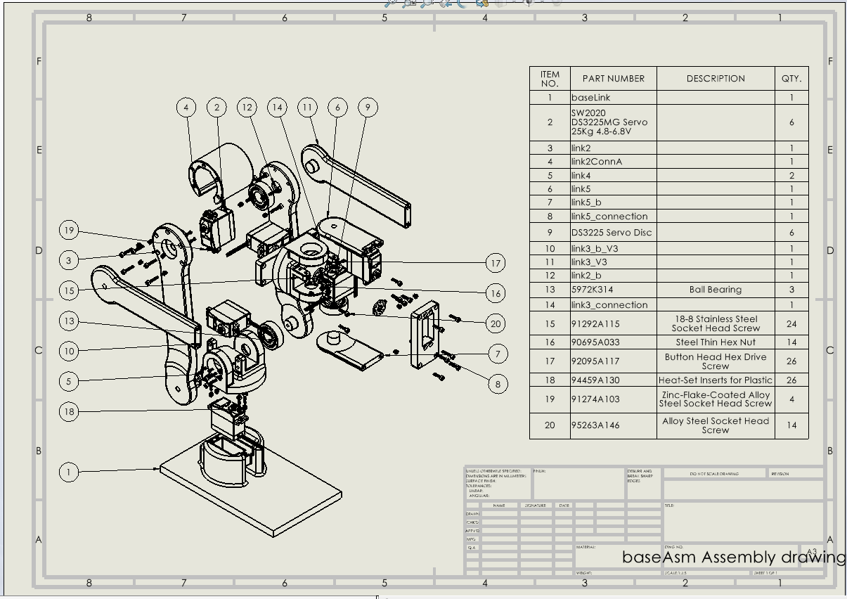
The solution combines a removable wheelchair mount, a multi-joint manipulator with modular end effector, and a low-effort control and feedback interface. Safety, comfort, appearance, vibration, reach, and caregiver access were treated as engineering requirements rather than afterthoughts.
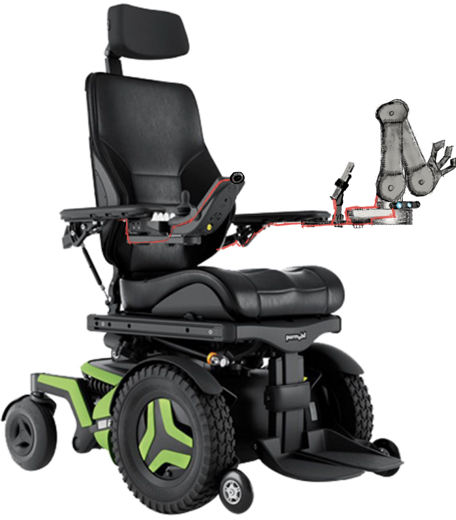
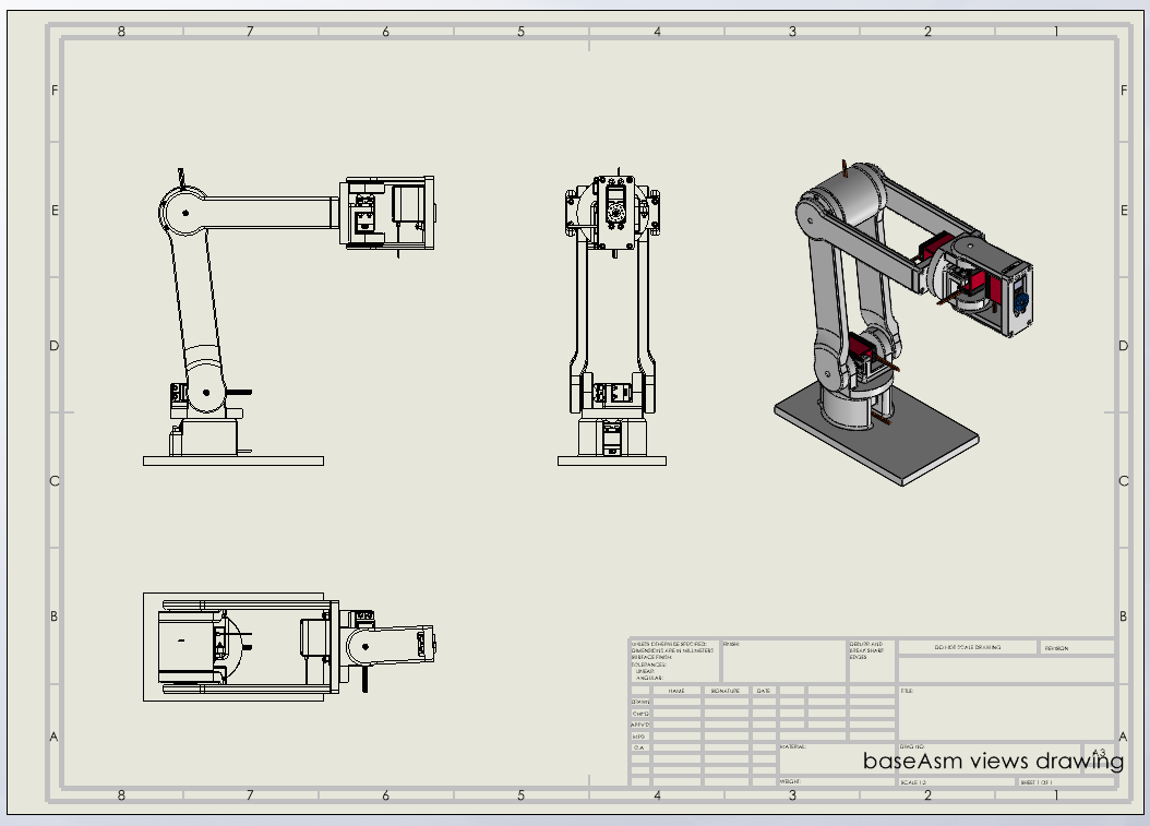
The early functional prototype used four degrees of freedom and a stylus to validate autonomous button actuation. The final system moved to six serially controlled servos, 6061 aluminum links, a removable armrest mount, and a distributed compute architecture.
Low-cost prototype servos jittered and lacked torque at full extension. Those findings drove the stronger mechanical design and the move to UART servo control in the final arm.
The interface gives the user a direct view of the robot’s available actions and current state. Its task-oriented interaction model reduces the number of physical inputs and avoids forcing the user to manually coordinate individual joints.
The video demonstrates the working HMI and its role in making autonomous functions understandable and predictable.
The final architecture used an Intel RealSense depth camera with a Raspberry Pi 5 and AI HAT for perception and high-level decision-making. An Arduino Sense controller handled the real-time control layer, while the six servos received position commands over a serial UART bus. This separation kept compute-intensive vision away from timing-sensitive motion control.
The earlier demonstration shown here used a ZED 2, AprilTags, a Jetson Nano, and an Arduino-based servo controller to validate autonomous elevator-button targeting. A hard-wired emergency stop provided an immediate physical shutdown during testing.
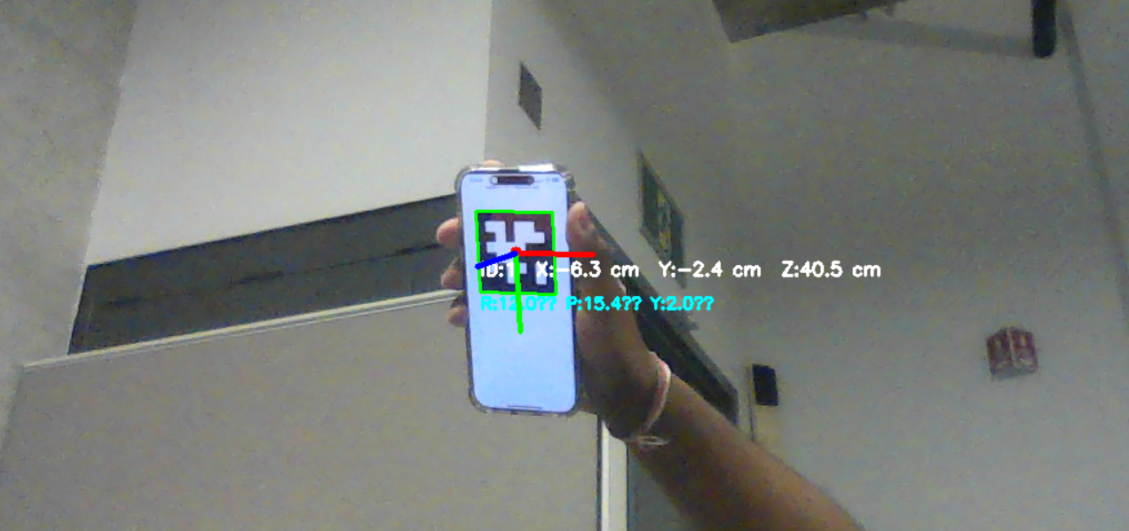
Power and vision modules passed their initial tests, including accurate AprilTag localization. Low-cost prototype servos introduced torque limitations and jitter at full extension, but calibration enabled the integrated arm to autonomously detect and actuate the target buttons—validating the overall system logic.
Raspberry Pi 5 · AI HAT · Intel RealSense · Arduino Sense · UART servo control · Python · OpenCV · inverse kinematics · SolidWorks · FEA · DFM · FMEA
One mobile robot iterated across three escalating challenges—from rapid terrain traversal to multi-package navigation inside a structured maze.
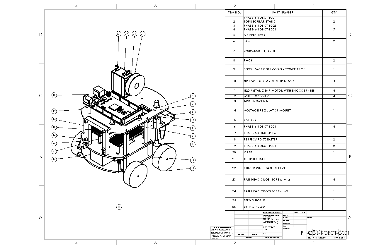
The APDR was intentionally developed as one continuous system. Each phase retained the four-wheel platform and closed-loop drive while adding new terrain, manipulation, sensing, and navigation demands. Parametric SolidWorks models, FDM manufacturing, modular connectors, and shared mechanical interfaces made rapid redesign practical between demonstrations.
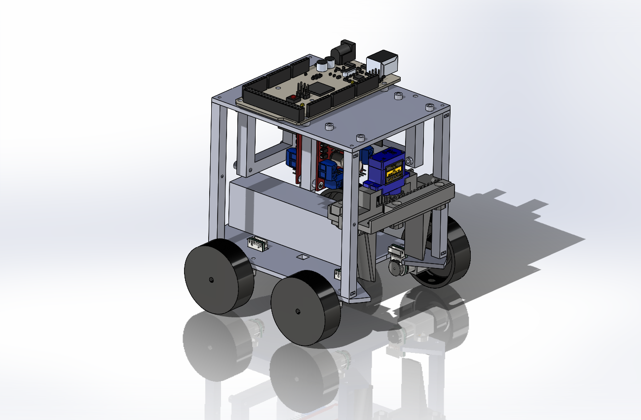
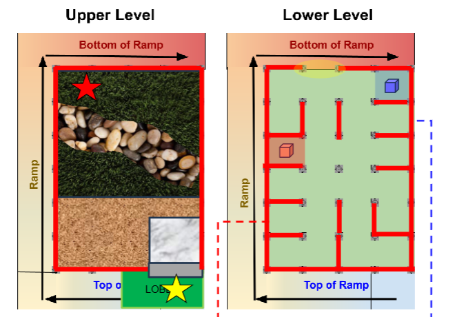
Cross grass, pebble, and mulch; drive onto the target platform; and release a package using encoder-based PID control.
Add ramp travel, wall-following, maze entry, ToF sensing, and a pulley-driven lifting gripper to retrieve a block.
Integrate IMU and ToF fusion, ESP32 vision, A* path planning, PD correction, revised electronics, and two-package handling.
Phase A used encoder feedback and per-wheel PID loops for straight driving and in-place turns. Phase B introduced event-driven wall following with distance sensors. Phase C combined IMU heading, filtered ToF measurements, PD corrections, vision-assisted package alignment, and an A*-generated route through the known maze.
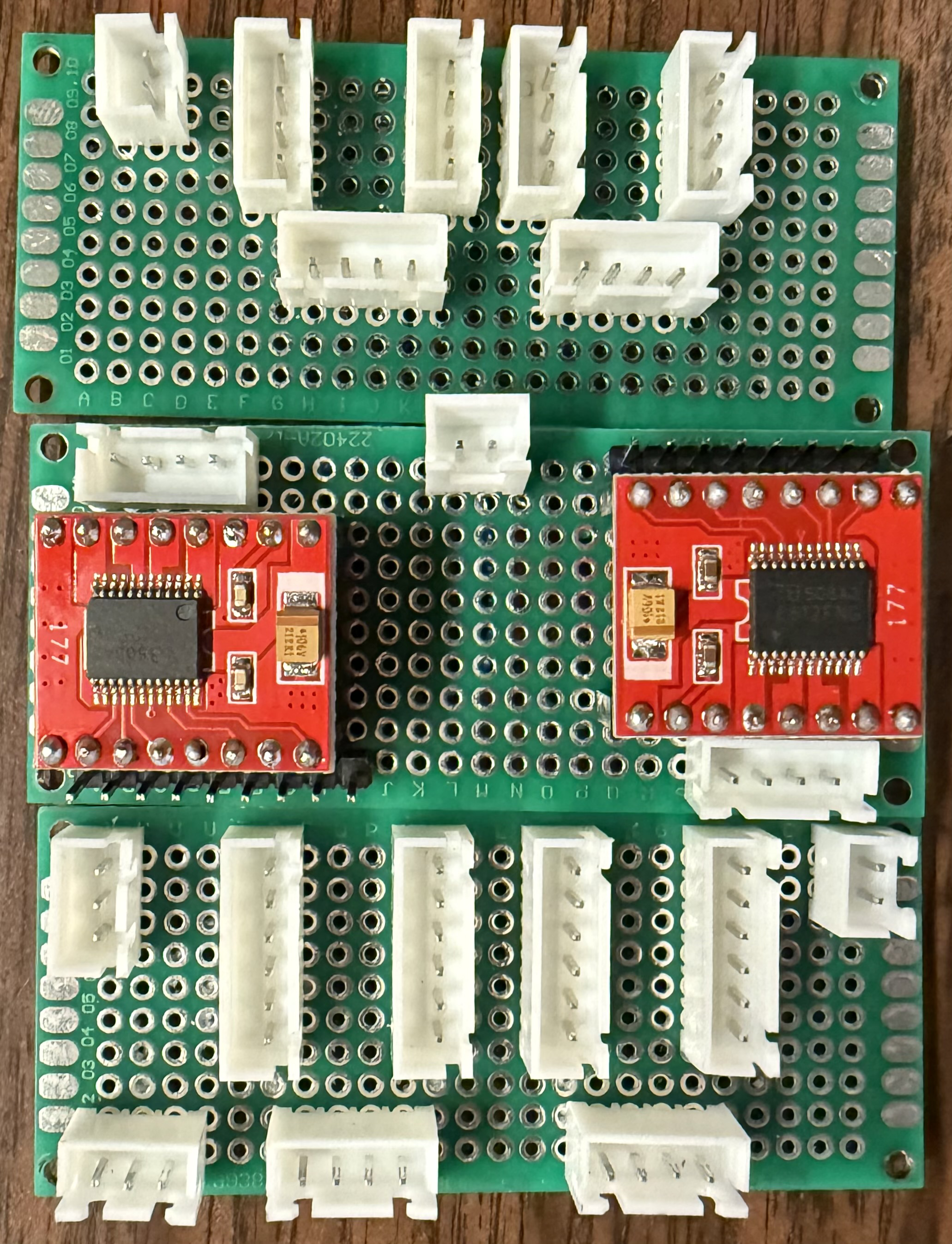
Wiring noise and last-minute hardware faults in Phase B directly shaped the Phase C rebuild. The team revised the distribution boards, separated power and signal paths, standardized JST connections, improved wire management, and added serviceable sensor mounts.
The mechanical platform evolved in parallel with a rack-and-pinion gripper, pulley lift, ESP32 camera mount, and lightweight printed geometry designed around ±0.2 mm manufacturing tolerances.
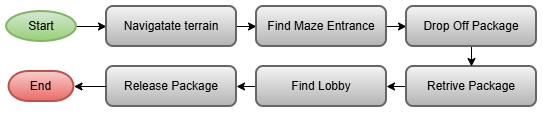
Three levels of testing separated sensor and actuator accuracy from navigation performance and full-mission behavior. This made failures traceable and quantified the gains from the final sensor-fusion architecture.
Phase B was not a dead end—it revealed exactly what the final system lacked.
The three-phase structure made reliability visible. The final robot integrated more capable mechanics, electronics, and software than the initial platform, but the official run also exposed how small heading and distance errors accumulate across long autonomous sequences. The project closed with a clear next step: stronger localization and longer-duration sensor-fusion testing.
SolidWorks · Arduino Mega · ESP32-CAM · C/C++ · PID/PD control · IMU · ToF sensing · A* path planning · custom PCBs · FDM printing · FMEA
A 2024 academic design study integrating power electronics, two-axis actuation, and closed-loop control for a simulated 100 kg tracking platform.
The course project modeled the interaction between electrical power delivery, azimuth and elevation actuators, and a feedback controller. Requirements included supporting a 100 kg load, acquiring feasible target trajectories, and keeping the target near the camera centre. The submitted work was a design and simulation study rather than a fabricated turret.
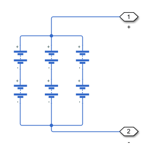
Six 25.4 V, 166 Ah battery models were arranged as three parallel strings of two series-connected batteries, producing a modeled 50.8 V, 498 Ah source. A boost-converter stage was sized around an 83.7% duty cycle and 600 kHz switching frequency, with calculated inductance, capacitance, ripple, and semiconductor requirements.
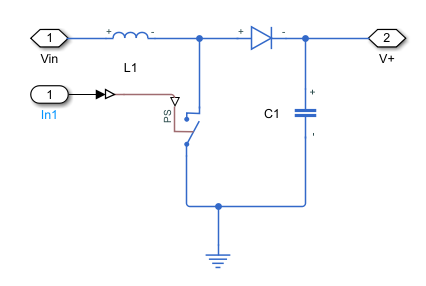
The design calculated a 1.67 µs switching period, 1.39 µs pulse width, 9.6 A allowable current ripple, and 3.11 V allowable voltage ripple. The resulting model used a 1,920 µH inductor and 13 µF output capacitor, followed by component selection against the simulated electrical stresses.
Early full-detail Simscape models produced algebraic-loop issues and simulation times ranging from more than 30 minutes to over an hour. The final architecture represented the BLDC motor and power stage with reduced-order transfer functions, cutting execution to milliseconds and allowing MATLAB PID Tuner to be used iteratively.
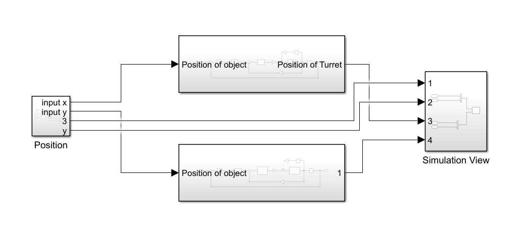
The final 20-second simulation included motor parameters, load, Gaussian measurement noise, a 5.6 kHz low-pass filter, and tuned PID control. The report records the simulated response as reaching within ±2° of the moving target within four seconds.
MATLAB · Simulink · Simscape · PID Tuner · BLDC motor modeling · DC-DC conversion · battery architecture · component sizing
The case studies document requirements, development decisions, testing, and observed results.
Identify user needs, operating constraints, performance targets, and technical risks.
Compare concepts, model key behavior, build subsystems, and integrate the selected design.
Measure performance, record failures, implement revisions, and report the final results.
Manufacturing, qualification testing, laboratory operations, and controlled technical documentation.
Conference work related to the educational reactor simulator developed at Ontario Tech University.
44th Annual CNS Conference and 49th CNS/CNA Student Conference · Toronto, Ontario · June 8–11, 2025
The paper documents a physical CANDU educational simulator that combines adjustable control rods, precomputed OpenMC neutron-flux distributions, an Arduino interface, and an LED lightboard to make reactor behavior visible during laboratory instruction.
View publication on ResearchGatePeter Marchut is a Mechatronics Engineering graduate from Ontario Tech University with project experience across mechanical design, embedded control, instrumentation, automation, and system testing.
His engineering experience includes nuclear manufacturing, undergraduate laboratory operations, multidisciplinary robotics, qualification testing, technical documentation, and hands-on troubleshooting.
Ontario Tech University · April 2026
CSWA · 2021
Real-time embedded systems · automatic control · industrial automation · sensors and instrumentation · robotics and automation · actuators and power electronics · CAD · microprocessors and digital systems
Mechatronics engineering · embedded systems · automation · controls · manufacturing · testing
View résumé